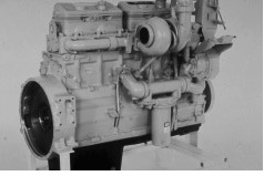
Caterpillar 3406B Engine
The Caterpillar 3406A was introduced in 1973. Since then, a number of changes have been made to meet the demand for an even more reliable and economical product, while meeting governmental regulations. The 3406B, released in 1983, is an example of these changes. The major change to this engine was the fuel system. The New Scroll Fuel System had been in production since 1980 on the 3300 engines. This fuel system is a key factor in the emissions, performance and fuel economy improvements in the 3406B. In 1991, the fuel system was changed to incorporate a more aggressive fuel camshaft to improve emissions. In 1992 the 3406C was introduced. There were no changes to the mechanical fuel system.
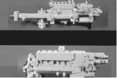
Caterpillar 3406 Fuel Injection Pump Groups
In the top view we can see how the 3406A Engine Fuel Injection Pump had a long drive because there wasn’t room for the pump housing under the air compressor. In the lower view we see the 3406B/C Fuel Injection Pump. It is shorter, but more massive. The shorter length of the 3406B/C pump leaves more room for servicing.
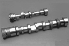
Injection Pump Camshafts
Many of the changes and improvements were internal, and can’t be seen. Here we see the fuel injection pump camshafts. The 3406A is at the top. The 3406B camshaft below it is larger and heavier, and is driven by a gear on the left end. The 3406B cams have a different configuration-they have a faster lift and shorter duration, increasing fuel injection pressures and reducing the time of injection, for greater fuel efficiency. An eccentric on the camshaft operates the piston-type fuel transfer pump. With the changes for emissions in 1988, the nose of the camshaft changed. The 10 degrees helix on the front was changed to a 15 degrees helix and the hole in the front was enlarged to accommodate a different timing advance unit. The emission changes for 1991 was a bearing diameter and lobe shape change only.
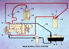
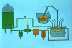
This is a schematic of the 3406B/C engine fuel system. We’ll use the schematic to follow the flow of fuel from the supply tank to the injector in the cylinder. The transfer pump (5) pulls fuel from the fuel tank (1) through the supply shutoff valve (3) through the primary fuel filter (4) to the fuel transfer pump itself. The transfer pump then pressurizes the fuel and pushes it though the hand priming pump (7), into the secondary fuel filter (6) and into the fuel manifold (8) under moderate pressure. A bypass valve inside the fuel transfer pump maintains moderate fuel pressure. With moderate fuel pressure inside the fuel manifold and the void (vacuum) inside the high pressure pumps, the fuel is loaded into the cavity of the high pressure pump.
The high pressure pumps now meter a small amount of fuel and sends it though the high pressure fuel lines (9) and through the head adapter
(10) to the injection nozzle (11) at a very high pressure. When the fuel pressure in the high pressure fuel lines gets above the nozzle opening pressure the fuel is injected into the combustion chamber. With both very high pressure and very small holes in the tip of the nozzle, the fuel is atomized and gives complete combustion in the cylinder. Any air and some fuel is sent out of the fuel manifold through the return line (15) back to the supply tank. The tank drain
(2) is used to remove water, sediment and foreign material and to drain the supply tank. The fuel tank cap (16) must be vented to atmosphere to keep vacuum from forming inside the fuel tank.
3306 Fuel Flow
This is a schematic of the 3306B/C engine fuel system. We’ll use the schematic to follow the flow of fuel from the supply tank to injection in the cylinder. The transfer pump (6) pulls fuel from the fuel tank
(9) through the supply shut off valve (3) through the primary fuel filter (4) through the hand priming pump (5) into the transfer pump itself. The transfer pump then pressurizes the fuel and pushes it through the secondary fuel filter (7) and to the fuel manifold in the injection pump housing (8). A bypass valve inside the fuel transfer pump maintains moderate fuel pressure. With moderate fuel pressure inside the fuel manifold and the void (vacuum) inside the high pressure pumps, the fuel is loaded into the cavity of the high pressure pump. The high pressure pumps now meter a small amount of fuel and sends it though the external high pressure fuel lines (9) at a very high pressure to the fuel injection nozzle (10). When the fuel pressure in the high pressure fuel lines gets above the nozzle opening pressure the fuel is injected into the combustion chamber. With both very high pressure and very small holes in the tip of the nozzle, the fuel is atomized and gives complete combustion in the cylinder. A constant bleed valve (11) lets a constant flow of fuel go through the fuel return line (12) back to the fuel tank (1). This helps keep the fuel cool and free of air. There is also a manual bleed valve that can be used when the fuel priming pump is used to remove air from the system. The supply tank drain (2) is used to remove water, sediment, foreign material and to drain the supply tank. The fuel cap must be vented to atmosphere to keep a vacuum from forming inside the fuel tank.
Most un helpful and confusing web sight ive ever used.