(PEEC) System Overview
The 3406B PEEC Diesel Truck Engine is an electronically-controlled 3406B. The Electronic Control Module (ECM) for the engine controls fuel rate and timing electronically instead of using the flyweights and linkages of a mechanical governor. The electronics also replace the mechanical fuel-air ratio control, torque control group, and various adjustment screws.
The PEEC fuel system uses several sensors as inputs to control two basic functions: fuel rack position and fuel injection timing. The operation of each of these are similar. The ECM decides where it wants to position the rack or the timing advance. The ECM then varies the voltage to the appropriate Brushless Torque Motor (BTM) to move the rack or the timing toward the desired position. The rack and the timing have two separate BTMs. Position sensors tell the ECM when rack or timing is at the desired position.
Descriptions of System Components
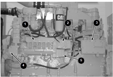
- Electronic Control Module (ECM) (3): This is the control computer for the The ECM receives information from various input sensors, stores operating data, processes input, and controls the various output devices. The ECM has the ability to perform self diagnostics on the engine, and log any faults that may occur.
- Personality module: The personality module is a component of the ECM that contains the rating information for the engine. This is what determines the fuel settings and consequently how much power an engine will
- Wiring Harness: Provides the electrical connections between the various components of the
- Service tool connector: Used for the technician to communicate with the engine electronics using an electronic service tool such as Electronic Technician (ET). Early Caterpillar electronic engines, including PEEC engines, used the Electronic Control Analyzer and Programmer (ECAP) to communicate with the electronics of the engine. ET is the current electronic service tool of choice for Caterpillar engines.
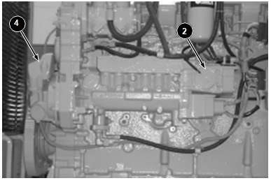
- Rack actuator (2): The solenoid is a Brushless Torque Motor (BTM) that is controlled by the The rack BTM is mounted on the side of the governor housing that is on the rear of the injection pump. The rack BTM operates the fuel control rack in the fuel injection pump.
- Rack position sensor: Provides feedback information to the ECM about the position of the fuel control rack.
- Timing advance unit (4): The timing advance unit contains the timing advance solenoid, the timing position sensor, and the helical advance years that control the timing of the fuel injection This solenoid is a Brushless Torque Motor (BTM) that controls the valve that regulates the hydraulic pressure which in turn changes injection pump timing. This is often referred to as the timing BTM.
- Timing position sensor: Provides feedback information to the ECM about the position of the timing advance unit.
- Transducer module (5): Contains the engine oil pressure sensor, the boost pressure sensor, and the inlet air pressure This component is mounted on the rear of the injection pump.
- Throttle position sensor: Produces a Pulse Width Modulated (PWM) signal to the The throttle position sensor is connected to the throttle linkage or accelerator pedal.
- Engine speed sensor: This sensor magnetically senses the speed of the engine from the grooves in a chopper wheel that is mounted on the rear of the injection pump The sensor sends a signal to the ECM.
- Vehicle speed sensor: This sensor magnetically senses the speed of the vehicle from a toothed (chopper) wheel on the output of the The sensor sends a signal to the ECM.
- Vehicle speed buffer: This conditions the signal from the vehicle speed sensor and provides a signal to the ECM and in some applications, the speedometer of the vehicle as
- Diagnostic lamp: Sometimes referred to as the “check engine light”. This light flashes in five second intervals and displays any active codes that may be present.
- Cruise control switches: Used to set the cruise control and to retrieve any logged fault codes that may be
- Fuel injection pump (1): A high pressure pump that delivers variable quantities of fuel to a nozzle.
Operation of the Fuel Rack Position Mechanism
The rack mechanism on a PEEC engine is very similar to a mechanical 3406B engine. The fuel injection pump is nearly identical; the rack is moved by a servo valve which receives oil pressure from the fuel injection pump. However, the servo spool is moved by the rack actuator (2), sometimes called therack BTM rather than by a linkage controlled by flyweights and springs.
The ECM determines a “desired rpm” based on the throttle position, vehicle speed, Customer Specified Parameters, and certain diagnostic codes. The ECM attempts to maintain the desired rpm by sensing actual engine rpm using the engine speed sensor, then controlling the rack to achieve the desired rpm.
In order to move the rack, the ECM adjusts the voltage to the rack BTM to increase or decrease rack. More voltage results in more rack. The ECM knows how far the rack actually went by feedback information from the rack position sensor. The ECM increases or decreases the voltage to the rack BTM until it senses that the rack is in the desired position.
Operation of the Timing Advance Unit
Timing advance unit (4) contains the timing advance solenoid, the timing position sensor, and the helical advance gears for the timing of the fuel injection pump. The timing advance mechanism is the same as the 3406B mechanical engine, except the timing BTM controls amount of timing advance instead of flyweights. The ECM adjusts voltage to the timing solenoid to change timing advance. More voltage results in more timing advance. The ECM knows how much advance was actually achieved by feedback information from the timing position sensor. The ECM simply increases or decreases voltage to the timing solenoid until it senses that the timing advance is in the desired position.
Desired timing advance is controlled by software in the Personality Module, and is dependent on engine rpm, load, and other operation factors. Because of this, the performance specifications do not call out the amount of advance at a specific rpm. The best indication of timing advance specification is displayed on the status screens of the electronic service tool as “Des Timing Adv.”
Programmable Parameters
Certain parameters that affect PEEC engine operation may be changed through the use of electronic service tools. The parameters are stored in the ECM, and are protected from unauthorized changes by passwords.
As an example, Vehicle Speed Limit (VSL) is programmable to allow the customer to electronically limit vehicle speed. When the programmed limit is reached, the ECM limits rpm so that VSL will not be exceeded. Also, Progressive Shift parameters (such as Low Gear limits and High Gear limits) will cause the ECM to limit engine speed at a programmed engine rpm to encourage more fuel-efficient driving practices.
Passwords
“System Configuration Parameters” are protected by factory passwords. System Parameters are those that affect horsepower family or emissions. Factory passwords are calculated on a computer system available only to Caterpillar dealers. Since factory passwords contain alphabetic characters, only ECAP or ET may change System Parameters.
“Customer Specified Parameters” are protected by customer passwords. Customer Parameters are those that affect cruise control, vehicle speed limits, progressive shifting, horsepower rating within a family, and PTO operation. The customer passwords are programmed by the customer. Either ECAP or ET may normally change Customer Parameters.
Self-Diagnostics
The PEEC fuel system has some ability to diagnose itself. When a problem is detected, a diagnostic code is generated and the diagnostic lamp is turned on. On newer engines (those equipped with personality modules built since April 1989), the code may also be stored in permanent memory in the personality module.
Diagnostic Codes that represent current faults are called ACTIVE. They indicate that a problem of some kind currently exists. They should always be serviced first.
Diagnostic Codes stored in memory are called LOGGED. The problem may have been temporary or may have been repaired since the time it was LOGGED. Therefore, LOGGED diagnostic codes don’t necessarily mean something needs to be repaired. They are meant to be an indicator for when intermittent problems exist. In addition, some logged diagnostic codes record “events,” rather than failures.