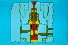
3406 Injection Pump
The area shown in red is the fuel gallery of the 3406B/C fuel pump. This area is pressurized by the fuel transfer pump. The cutaway shows the placement of the pump groups within the pump housing. Fuel enters and leaves the pump group by way of the hardened hollow dowel. This dowel is in the housing to protect it from erosion caused by the high pressure spill pulses.
3306 Injection Pump
This is a cutaway of a similar area of the 3306B/C fuel pump. Notice the similarity of the two different pumps.
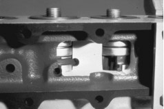
3406 Fuel Rack
The area shown in the slide is a cutaway of the engine side of the 3406B/C fuel pump housing. This cutaway shows a complete pump in the center and a cutaway pump on the right. We can see the relationship of the pump groups and the rack as the gear segment engages the rack. Also note the lifters and return springs.
>
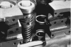
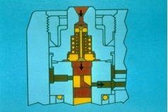
Fuel Metering
We’ll use a cutaway pump to see how fuel is metered and delivered to the fuel injection nozzles. This is a scroll type fuel system with a left-hand cut scroll on the pump plunger. The gear on the bottom of the plunger is engaged into the rack. Rack movement rotates the plunger in the pump barrel and changes the relationship of the scroll to the spill port (arrow). The camshaft/follower/lifter mechanism moves the plunger up and down in the barrel. In this position, the plunger is at the bottom of its stroke. Fuel is coming into the barrel through the spill port in the back side of the barrel and through the fill port.

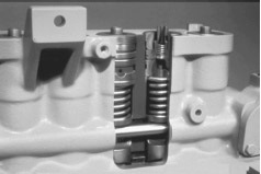
Fuel Delivery
Now, the cam has lifted the plunger so the fill port and spill port are just closed. This is the start of the effective stroke of the plunger and the beginning of injection. As the fuel in the barrel is pressurized, the reverse flow check valve is lifted off its seat in the pump bonnet.
This sends pressurized fuel through the fuel lines to the injection nozzle. Injection continues until the end of the effective stroke, when the scroll in the plunger lines up with the spill port in the barrel.
End of Fuel Delivery
At the end of the effective stroke, the spill port is opened by the scroll, fuel pressure is released and the reverse flow check valve closes. During the entire pumping cycle the groove on the plunger is positioned over the bleed back passage.
Bleed Passage
When the groove in the plunger is in this position, it is aligned with the pressure bleed back passage in the barrel. This bleeds of fuel that goes between the barrel and the plunger and prevents fuel dilution in the engine oil.
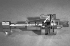
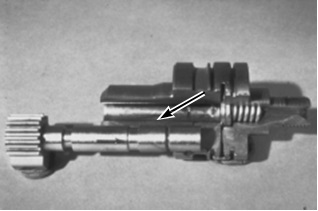
Reverse Flow Check Valve
The reverse flow check valve keeps the fuel injection line full of fuel between injection strokes. Pressurized fuel (approximately 1000 psi) is kept in the injection line, ready for the next pump stroke. When the engine and injection pump are stopped, the groove (arrow) bleeds the pressure in the injection line to equalize with the residual pressure in the pump.
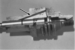
Reverse Flow Check Valve Operation
When fuel pressure in the barrel above the plunger reaches 100 psi, the valve is lifted off its seat and fuel flows out the cavity through the bonnet to the injection line. The check valve spring keeps the valve seated when fuel is at transfer pump pressure. This means that fuel can enter the injections lines only during the injection stroke, helping to eliminate cylinder wash down if an injection nozzle is stuck open.
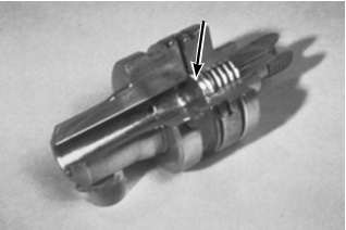
Reverse Flow Check Valve
Pressurization continues until the scroll opens the spill port and the pressure in the pump barrel is released. This seats the check valve, but the pressurized fuel in the injection line opens the return flow check valve. Fuel will return to the pump barrel and flow out the spill port until pressure in the injection line drops to 1000 psi. At that point, the return flow check valve spring will seat the valve. When the engine is shut off, a small groove in the face of the check valve allows the 1000 psi pressure to bleed off.