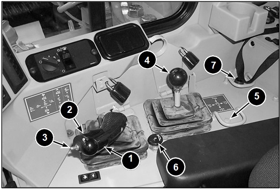
The dozer control lever (1) is located at the right of the operator’s seat. The standard implement control lever allows the operator to control all the blade functions from one lever. Pushing the lever to the forward detent position causes the blade to FLOAT. When the lever is in the forward position (just to the rear of FLOAT), the blade will LOWER. Pulling the lever to the rear of the center (HOLD) position causes the blade to RAISE. Pushing the lever to the right tilts the right side of the blade down, and pushing the dozer control lever to the left tilts the left side of the blade down.
With the dual tilt option, the dozer control lever also includes a trigger switch (2) and a toggle switch (3). Engaging the trigger switch and moving the lever to the right will cause the blade to tip forward for more blade penetration, and engaging the trigger switch and moving the lever to the left will cause the blade to tip rearward for greater dozing load. The toggle switch is used to operate either in the single tilt mode or the dual tilt mode. When the toggle switch is in the ON position (forward), the dozer will be in the dual tilt mode. When the toggle switch is in the OFF position (rearward), the dozer will function in the single tilt mode.
All machines are equipped with a ripper control lever (4) behind the implement control, even if a ripper is not installed. To RAISE the ripper, move the control lever toward the operator’s seat out of the center (HOLD) position, and to LOWER the ripper, move the control lever away from the operator’s seat out of the center (HOLD) position. To bring the ripper shank IN, move the control lever forward of the center (HOLD) position, and to move the ripper shank OUT, move the lever to the rear of the center (HOLD) position.
An optional pin puller is available for machines equipped with a single shank ripper. The pin puller switch location (5) is to the rear of the ripper control lever. The switch EXTENDS the pin if the switch is moved to the right, or RETRACTS the pin if the switch is moved to the left.
The horn button (6) is located between the implement control lever and the ripper control lever.
Located at the right rear of the console is an action lamp (7) to alert the operator of a system that is operating out of normal range.
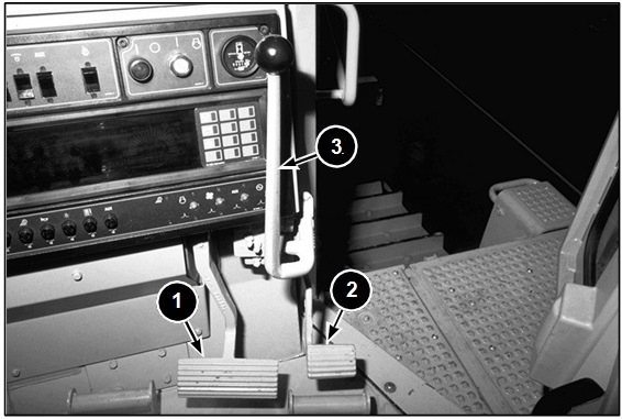
Both the steering clutch and brake and the differential steer models are equipped with two pedals. Depressing the large pedal (1) ENGAGES the service brakes. The smaller pedal is the decelerator pedal (2). During normal operation, the operator moves the governor control lever (3) into the HIGH IDLE position and decreases the engine rpm using the decelerator pedal to control engine speed for directional shifts, modulated steering, and precise grading control of the blade.